AutoHotkey | Android | Arduino | COMM140 | Fractals | Grammar Checkers | Knots | A Million Dots Activity | Processing | Processing for Scratch Users | Redbubble | Tutorials | Weather | World Time Meeting Planner | Favicon Generator.
Home > Tutorials > Auduino > Arduino UNO Demo >Tutorial for the Interactive Music Project
Home > COMM140 >Tutorial for the Interactive Music Project
Prototype Interactive Keyboard from rupert.russell on Vimeo.
Start with the basics.
1) If you need to download and install the Adruino IDE Integrated Development Environment from https://www.arduino.cc/en/Main/Software
Once you have downloaded and installed the software:
2) Connect the Arduino to the computer
3) Run the Adruino IDE
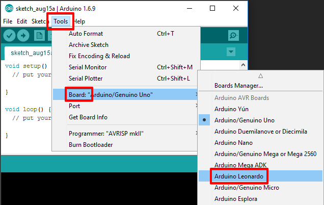
4) Select the correct board type within the IDE for this example I am using an Arduino Leonardo
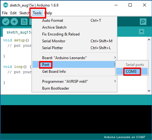
5) Identify and select the correct COM port
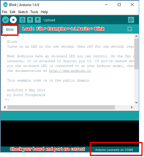
6) Load the example Blink program.
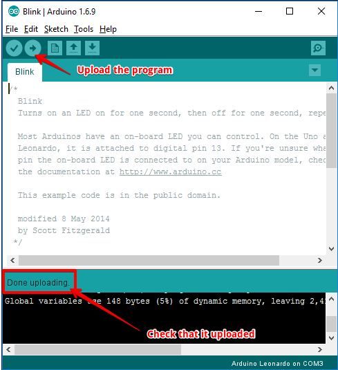
7) Upload the progam and make sure the Arduino in blinkng on and off every second
8) Check that the board it working properly
blink from rupert.russell on Vimeo.
Once we are happy that we can talk to the board and that it is running properly we can tank the next step
which is this case is to connect 2 switches and demonstrate that we can read the stwitchs and respon to them being pressed.
The following example may look a little messy see the Fritzing drawing for simpler to follow diagram of the layout
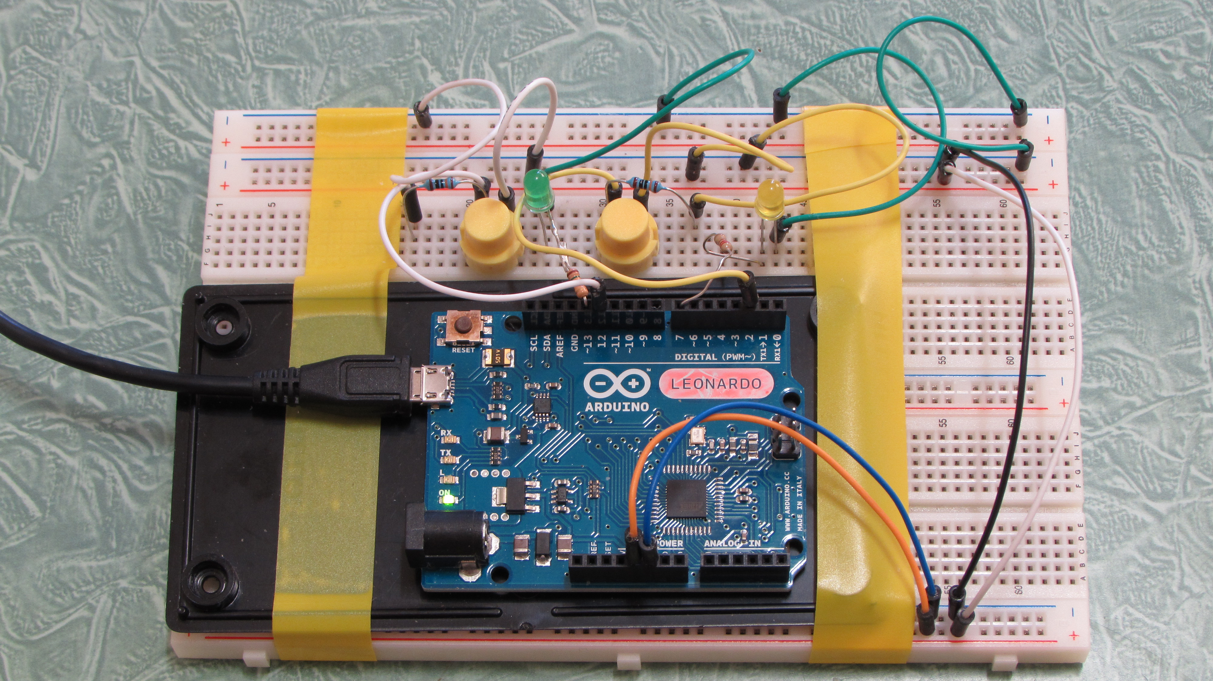
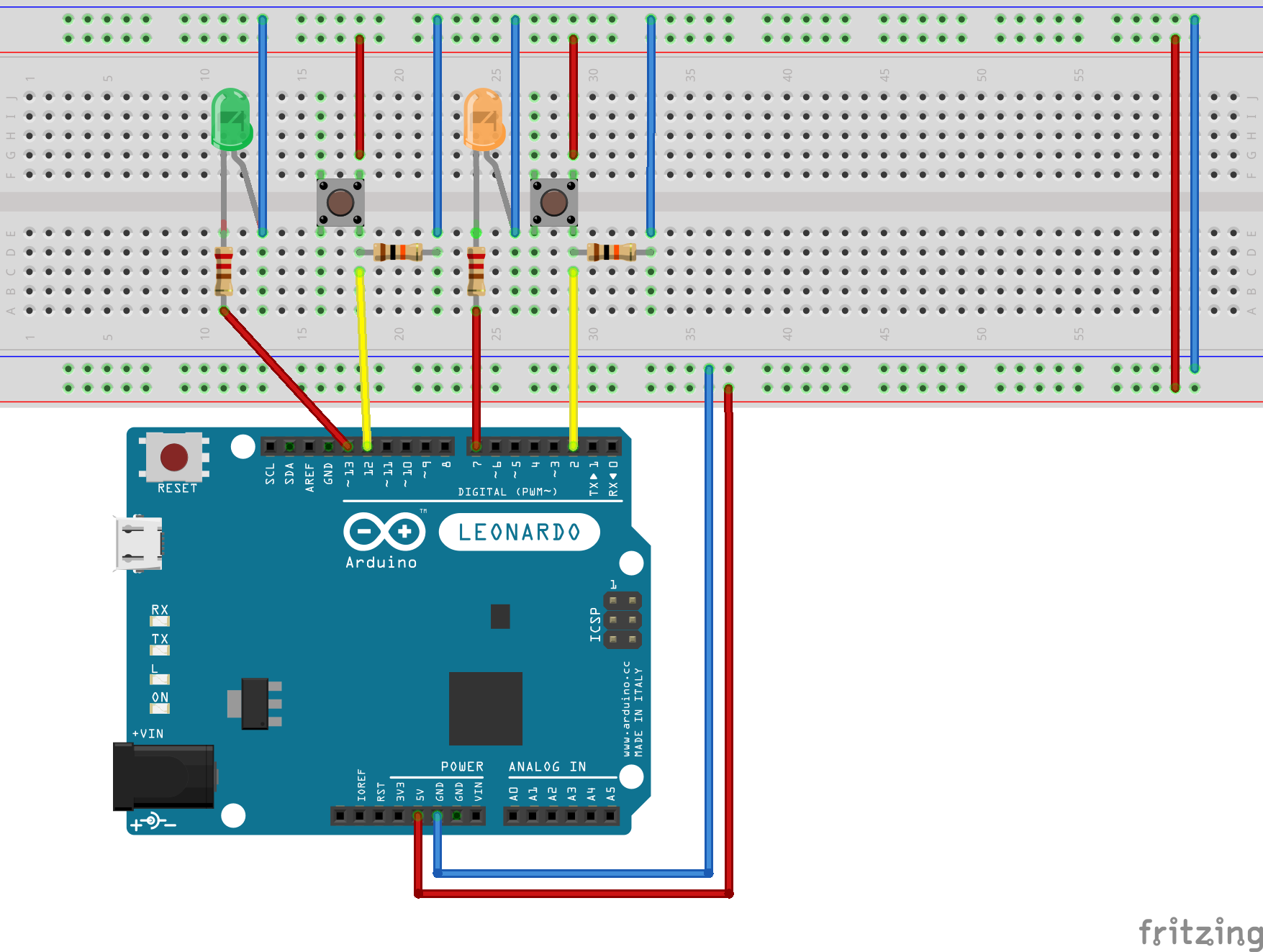
Each input on pin 2 & pin 12 is held Low via a 10K ohm resistor, this stops the value on the input from drifting high if the button is not presssed.
When the user presses the button it connects the input to + 5V and drives the input High.
Each LED has 220 Ohm a resistor in series to reduce the brightness of the LED which will stop it buring out.
The program sets up 2 inputs one on pin 2 and the other on pin 12
It set up 2 outputs one on Pin 7 and the other Pin 13
If the input on Pin 2 goes High then the program drives the output on Pin 7 High otherwise it drives Pin 7 Low
If the input on Pin 12 goes High then the program drives the output on Pin 13 High otherwise it drives Pin 13 Low
It repeat this process indefinatly
This allows us to test that we have sucesfully programed and wired up 2 switches.
For you project I expect you will want 8 switches one for each note on the scale
switches from rupert.russell on Vimeo.
/*
Button
Turns on and off a light emitting diode(LED) connected to digital
pins 7 & 13, when pressing a pushbutton attached to pin 2 & 12.
The circuit:
LED attached from pin 13 to ground via a 220 Ohm resistor
LED attached from pin 13 to ground via a 220 Ohm resistor
pushbutton attached to pin 2 from +5V
10K resistor attached to pin 2 from ground
pushbutton attached to pin 12 from +5V
10K resistor attached to pin 12 from ground
Note: on most Arduinos there is already an LED on the board
attached to pin 13.
created 2005
by DojoDave <http://www.0j0.org>
modified 30 Aug 2011
by Tom Igoe
modified 15 Aug 2016
by Rupert Russell to run 2 leds & 2 switches
This example code is in the public domain.
http://www.arduino.cc/en/Tutorial/Button
*/
// constants won't change. They're used here to
// set pin numbers:
const int buttonPin_1 = 2; // the number of the pushbutton_1
const int ledPin_1 = 7; // the number of the LED_1 pin
const int buttonPin_2 = 12; // the number of the pushbutton_2
const int ledPin_2 = 13; // the number of the LED_2 pin
// variables will change:
int buttonState_1 = 0; // variable for reading the pushbutton_1 status
int buttonState_2 = 0; // variable for reading the pushbutton_2 status
void setup() {
// initialize the LED pins as an outputs:
pinMode(ledPin_1, OUTPUT);
pinMode(ledPin_2, OUTPUT);
// initialize the pushbutton pins as an inputs:
pinMode(buttonPin_1, INPUT);
pinMode(buttonPin_2, INPUT);
}
void loop() {
// read the state of the pushbuttons:
buttonState_1 = digitalRead(buttonPin_1);
buttonState_2 = digitalRead(buttonPin_2);
// check if the pushbutton_1 is pressed.
// if it is, the buttonState is HIGH:
if (buttonState_1 == HIGH) {
// turn LED on:
digitalWrite(ledPin_1, HIGH);
} else {
// turn LED off:
digitalWrite(ledPin_1, LOW);
}
// check if the pushbutton_2 is pressed.
// if it is, the buttonState is HIGH:
if (buttonState_2 == HIGH) {
// turn LED on:
digitalWrite(ledPin_2, HIGH);
} else {
// turn LED off:
digitalWrite(ledPin_2, LOW);
}
}
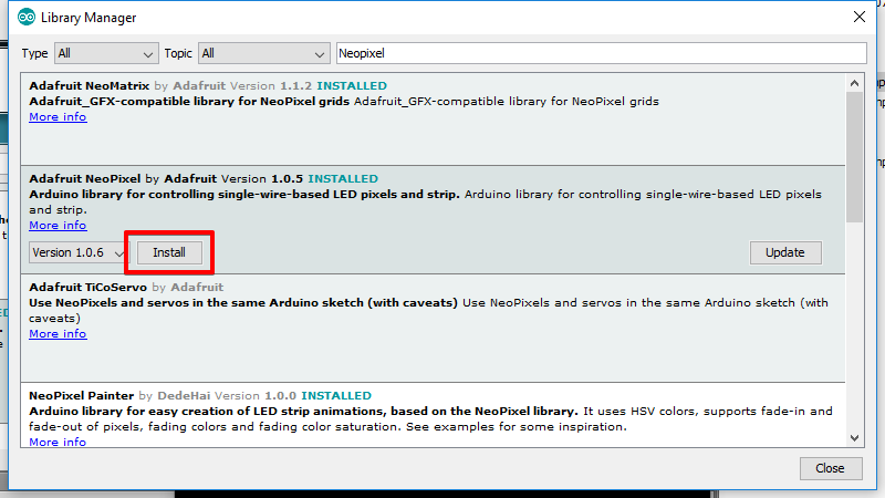
Next we progress from LEDs to Neopixes, this requies using a Library from Adafruit see below for how to load a library.
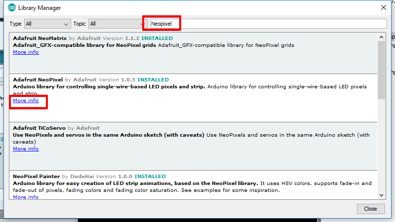
Sketch > Include Library > Manage Libraries...
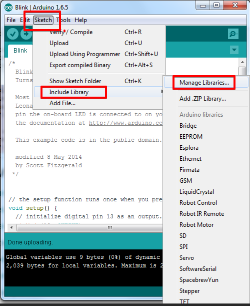
Search for Neopixel and insall the library
Next we add a pair of Neopixels to the hardware I have chosen to run these from Pin 11
NeoPixels for Music Project from rupert.russell on Vimeo.
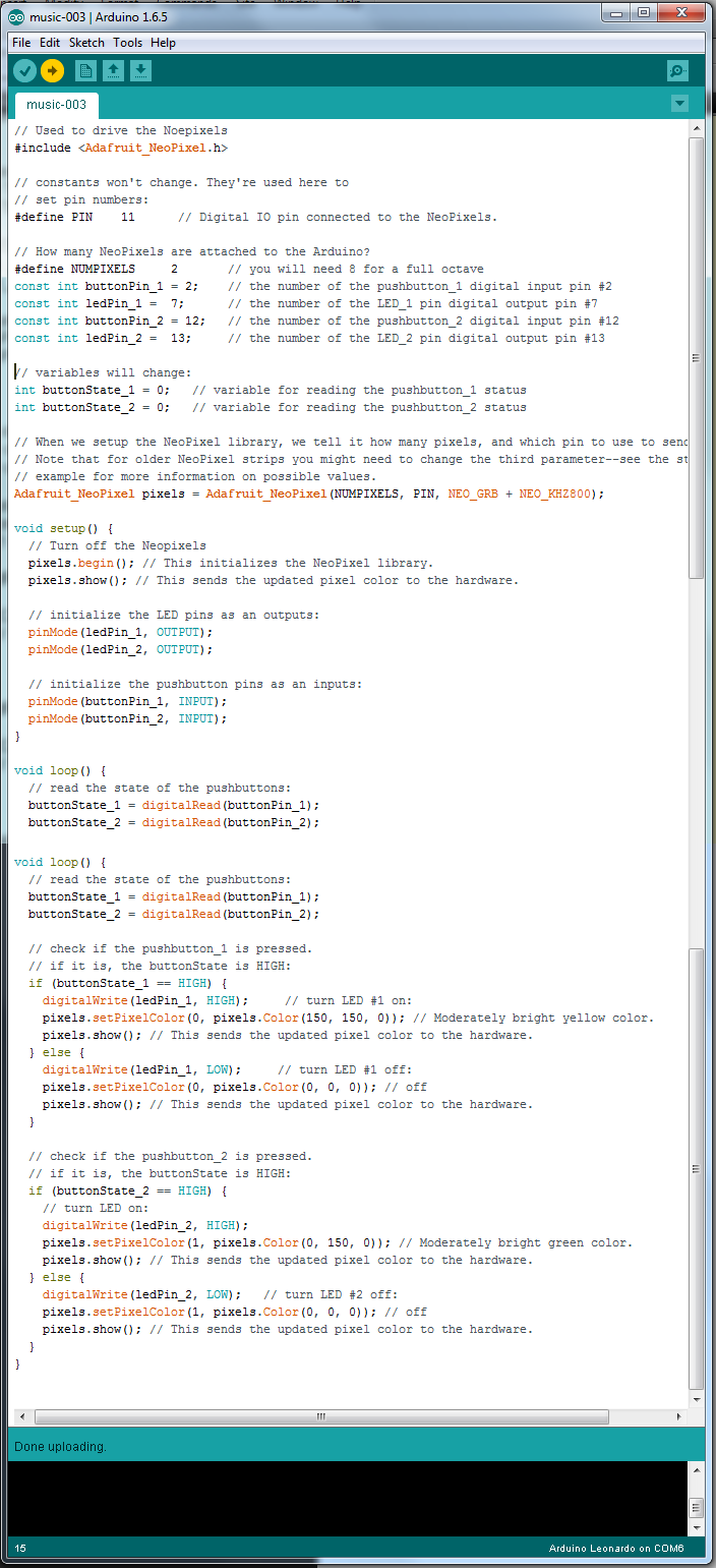
// constants won't change. They're used here to
// set pin numbers:
// Used to drive the Noepixels
#include <Adafruit_NeoPixel.h>
#define PIN 11 // Digital IO pin connected to the NeoPixels.
// How many NeoPixels are attached to the Arduino?
#define NUMPIXELS 2 // you will need 8 for a full octave
const int buttonPin_1 = 2; // the number of the pushbutton_1
const int ledPin_1 = 7; // the number of the LED_1 pin
const int buttonPin_2 = 12; // the number of the pushbutton_2
const int ledPin_2 = 13; // the number of the LED_2 pin
// variables will change:
int buttonState_1 = 0; // variable for reading the pushbutton_1 status
int buttonState_2 = 0; // variable for reading the pushbutton_2 status
// When we setup the NeoPixel library, we tell it how many pixels, and which pin to use to send signals.
// Note that for older NeoPixel strips you might need to change the third parameter--see the strandtest
// example for more information on possible values.
Adafruit_NeoPixel pixels = Adafruit_NeoPixel(NUMPIXELS, PIN, NEO_GRB + NEO_KHZ800);
void setup() {
// Turn off the Neopixels
pixels.begin(); // This initializes the NeoPixel library.
pixels.show(); // This sends the updated pixel color to the hardware.
// initialize the LED pins as an outputs:
pinMode(ledPin_1, OUTPUT);
pinMode(ledPin_2, OUTPUT);
// initialize the pushbutton pins as an inputs:
pinMode(buttonPin_1, INPUT);
pinMode(buttonPin_2, INPUT);
}
void loop() {
// read the state of the pushbuttons:
buttonState_1 = digitalRead(buttonPin_1);
buttonState_2 = digitalRead(buttonPin_2);
// check if the pushbutton_1 is pressed.
// if it is, the buttonState is HIGH:
if (buttonState_1 == HIGH) {
// turn LED on:
digitalWrite(ledPin_1, HIGH);
pixels.setPixelColor(0, pixels.Color(150, 150, 0)); // Moderately bright yelow color.
pixels.show(); // This sends the updated pixel color to the hardware.
} else {
// turn LED off:
digitalWrite(ledPin_1, LOW);
pixels.setPixelColor(0, pixels.Color(0, 0, 0)); // Moderately bright red color.
pixels.show(); // This sends the updated pixel color to the hardware.
}
// check if the pushbutton_2 is pressed.
// if it is, the buttonState is HIGH:
if (buttonState_2 == HIGH) {
// turn LED on:
digitalWrite(ledPin_2, HIGH);
pixels.setPixelColor(1, pixels.Color(0, 150, 0)); // Moderately bright green color.
pixels.show(); // This sends the updated pixel color to the hardware.
} else {
// turn LED off:
digitalWrite(ledPin_2, LOW);
pixels.setPixelColor(1, pixels.Color(0, 0, 0)); // off
pixels.show(); // This sends the updated pixel color to the hardware.
}
}
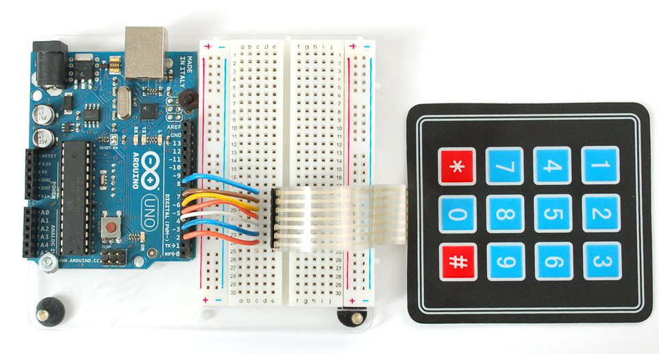
// This program uses a Keypad and echos out the keypresses to the keyboard using the Leonardo's virtual keyboard ability
// This will not work on an Arduino UNO compatiable board
// Inclu7de code from the Arduino library and the Keypad Library
#include "Arduino.h"
#include "Keypad.h"
// Set up the keypad
const byte ROWS = 4; //four rows
const byte COLS = 3; //three columns
char keys[ROWS][COLS] = {
{'1', '2', '3'},
{'4', '5', '6'},
{'7', '8', '9'},
{'*', '0', '#'}
};
byte rowPins[ROWS] = {8, 7, 6, 5}; //connect to the row pinouts of the keypad
byte colPins[COLS] = {4, 3, 2}; //connect to the column pinouts of the keypad
// Instantiate the keypad
Keypad keypad = Keypad( makeKeymap(keys), rowPins, colPins, ROWS, COLS );
// More definitions:
int LedPin = 13;
char key = keypad.getKey();
void setup() {
// put your setup code here, to run once:
Serial.begin(9600); // open the serial port at 9600 bps:
pinMode(LedPin, OUTPUT); // Make Digitital port #13 an output
// make pin 2 an input and turn on the
// pullup resistor so it goes high unless
// connected to ground:
pinMode(10, INPUT_PULLUP);
Keyboard.begin();
}
void loop() {
// put your main code here, to run repeatedly:
while (digitalRead(10) == HIGH) {
// Connect a wite from Grnd to Digital input 10 to run the program
// this is important because if you program a Leonardo
// to send keyboard output it can be hard to program it
// when you plug it into a computer because otherwise
// it can contunue to spit out characters
// do nothing until pin 10 goes low
delay(500);
}
// Read the key press
char key = keypad.getKey();
// Pressing the Number 1 key on the keypad will turn on LED #13
if (key == '1')
{
digitalWrite(LedPin, HIGH); // Turn on LED 13
Serial.println("1");
Keyboard.print("1");
}
// Pressing the Number 0 key on the keypad will turn off LED #13
if (key == '0')
{
digitalWrite(LedPin, LOW); // Turn off LED 13
Serial.println("0");
Keyboard.print("0");
}
}
// use with http://virtualpiano.net/
// see: http://www.freestylersupport.com/wiki/tutorial:sequences_ideas:rainbow_tutorial
// paino keys: s,d,f,g,h,j,k,l
// Include code from the Arduino library and the Keypad Library
#include "Arduino.h"
#include "Keypad.h"
#include "Keyboard.h"
#include <Adafruit_NeoPixel.h>
#define PIN 11
// How many NeoPixels are attached to the Arduino? There are 7 Neopixels in the Jewel
#define NUMPIXELS 1
Adafruit_NeoPixel pixels = Adafruit_NeoPixel(NUMPIXELS, PIN, NEO_GRB + NEO_KHZ800);
// Set up the keypad
const byte ROWS = 4; //four rows
const byte COLS = 3; //three columns
char keys[ROWS][COLS] = {
{'1', '2', '3'},
{'4', '5', '6'},
{'7', '8', '9'},
{'*', '0', '#'}
};
byte rowPins[ROWS] = {8, 7, 6, 5}; //connect to the row pinouts of the keypad
byte colPins[COLS] = {4, 3, 2}; //connect to the column pinouts of the keypad
// Instantiate the keypad
Keypad keypad = Keypad( makeKeymap(keys), rowPins, colPins, ROWS, COLS );
// More definitions:
int LedPin = 13;
char key = keypad.getKey();
void setup() {
// put your setup code here, to run once:
Serial.begin(9600); // open the serial port at 9600 bps:
pinMode(LedPin, OUTPUT); // Make Digitital port #13 an output
// make pin 2 an input and turn on the
// pullup resistor so it goes high unless
// connected to ground:
pinMode(10, INPUT_PULLUP);
Keyboard.begin();
pixels.begin();
pixels.show(); // Initialize all pixels to 'off'
}
void loop() {
// put your main code here, to run repeatedly:
while (digitalRead(10) == HIGH) {
// do nothing until pin 10 goes low
delay(500);
}
// Read the key press
char key = keypad.getKey();
// Pressing the Number 1 key on the keypad will turn on LED #13
if (key == '1')
{
digitalWrite(LedPin, HIGH); // Turn on LED 13
Serial.println("1");
Keyboard.print("s");
pixels.setPixelColor(0, pixels.Color(0, 255, 127)); // Light Green
pixels.show(); // This sends the updated pixel color to the hardware.
}
// Pressing the Number 2 key on the keypad will turn on LED #13
if (key == '2')
{
digitalWrite(LedPin, HIGH); // Turn on LED 13
Serial.println("2");
Keyboard.print("d");
pixels.setPixelColor(0, pixels.Color(0, 255, 255)); // Cyan
pixels.show(); // This sends the updated pixel color to the hardware.
}
// Pressing the Number 3 key on the keypad will turn on LED #13
if (key == '3')
{
digitalWrite(LedPin, HIGH); // Turn on LED 13
Serial.println("3");
Keyboard.print("f");
pixels.setPixelColor(0, pixels.Color(00, 127, 255)); // darker cyan color.
pixels.show(); // This sends the updated pixel color to the hardware.
}
// Pressing the Number 4 key on the keypad will turn on LED #13
if (key == '4')
{
digitalWrite(LedPin, HIGH); // Turn on LED 13
Serial.println("4");
Keyboard.print("g");
pixels.setPixelColor(0, pixels.Color(0,0, 255)); // blue
pixels.show(); // This sends the updated pixel color to the hardware.
}
// Pressing the Number 5 key on the keypad will turn on LED #13
if (key == '5')
{
digitalWrite(LedPin, HIGH); // Turn on LED 13
Serial.println("5");
Keyboard.print("h");
pixels.setPixelColor(0, pixels.Color(127, 0, 255)); // purple
pixels.show(); // This sends the updated pixel color to the hardware.
}
// Pressing the Number 6 key on the keypad will turn on LED #13
if (key == '6')
{
digitalWrite(LedPin, HIGH); // Turn on LED 13
Serial.println("6");
Keyboard.print("j");
pixels.setPixelColor(0, pixels.Color(255, 0, 255)); // magenta
pixels.show(); // This sends the updated pixel color to the hardware.
}
// Pressing the Number 7 key on the keypad will turn on LED #13
if (key == '7')
{
digitalWrite(LedPin, HIGH); // Turn on LED 13
Serial.println("6");
Keyboard.print("k");
pixels.setPixelColor(0, pixels.Color(255, 0, 127)); // Pink.
pixels.show(); // This sends the updated pixel color to the hardware.
}
// Pressing the Number 8 key on the keypad will turn on LED #13
if (key == '8')
{
digitalWrite(LedPin, HIGH); // Turn on LED 13
Serial.println("8");
Keyboard.print("l");
pixels.setPixelColor(0, pixels.Color(255, 0, 0)); // Red
pixels.show(); // This sends the updated pixel color to the hardware.
}
// Pressing the Number 0 key on the keypad will turn off LED #13
if (key == '0')
{
digitalWrite(LedPin, LOW); // Turn off LED 13
Serial.println("0");
Keyboard.print("0");
pixels.setPixelColor(0, pixels.Color(0, 00, 0)); // off.
pixels.show(); // This sends the updated pixel color to the hardware.
}
}
---
https://www.adafruit.com/product/2133
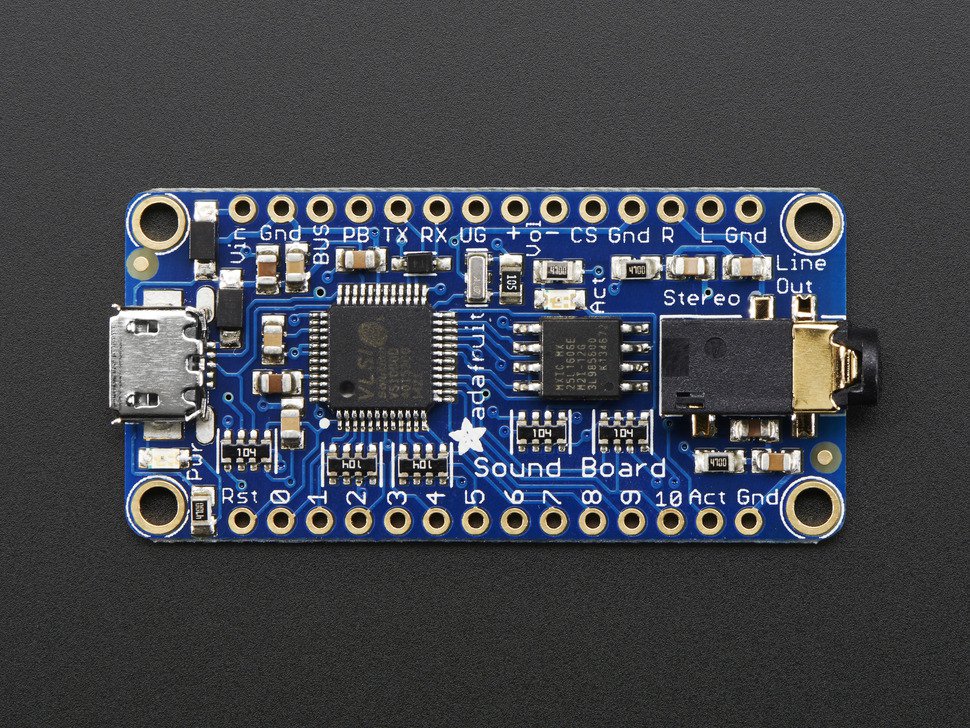
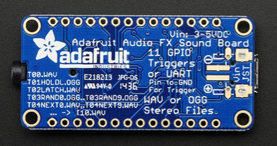
Note you have to unplug the battery to upload files
If the Battery is plugged in it charges and will not allow you to upload new Music Files to the Board
https://learn.adafruit.com/adafruit-audio-fx-sound-board/copying-audio-files
C Major Scale
https://www.freesound.org/people/digifishmusic/sounds/94812/
Local copy of the C Major Scale
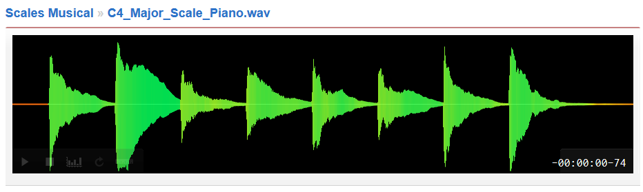
Use Audacity to cut it up
/*
Play 8 notes from T00 to T07
Using Pins 14 - 21 as outputs
*/
int timer = 1000;
// the setup function runs once when you press reset or power the board
void setup() {
// initialize digital pin 13 as an output.
pinMode(14, OUTPUT);
pinMode(15, OUTPUT);
pinMode(16, OUTPUT);
pinMode(17, OUTPUT);
pinMode(18, OUTPUT);
pinMode(19, OUTPUT);
pinMode(20, OUTPUT);
pinMode(21, OUTPUT);
digitalWrite(14, HIGH);
digitalWrite(15, HIGH);
digitalWrite(16, HIGH);
digitalWrite(17, HIGH);
digitalWrite(18, HIGH);
digitalWrite(19, HIGH);
digitalWrite(20, HIGH);
digitalWrite(21, HIGH);
// initialize serial:
Serial.begin(9600);
}
// the loop function runs over and over again forever
void loop() {
// loop from the lowest pin to the highest:
for (int thisPin = 14; thisPin < 22; thisPin++) {
// turn the pin on:
// turn the pin off:
digitalWrite(thisPin, LOW);
delay(timer);
digitalWrite(thisPin, HIGH);
delay(timer);
Serial.println(thisPin);
}
}
---
References:
https://www.freesound.org/people/digifishmusic/sounds/94812/